-
 Tel:
+86-15996094444
-
 E-mail:
INQUIRE NOW
+86-15996094444
INQUIRE NOW

Article Directory
A 20 mm slot in a stainless steel bracket absorbs more site error than any amount of re-surveying. Cast-in-place slabs commonly arrive 10 to 15 mm off the setting-out line under normal EN 13670 execution tolerances, and by the time that deviation reaches a 1.5 m cladding panel it has become a joint that is either too wide to seal or too tight to install.
The bracket is the only component in a facade that reconciles factory tolerance with site tolerance. Panels are cut and folded to plus or minus 1 mm. Slabs are not. Everything between those two realities is a bracket, an anchor and the joint between them, which is why bracket selection decides whether an exterior wall cladding system stays reliable for 25 years or starts leaking in the third.
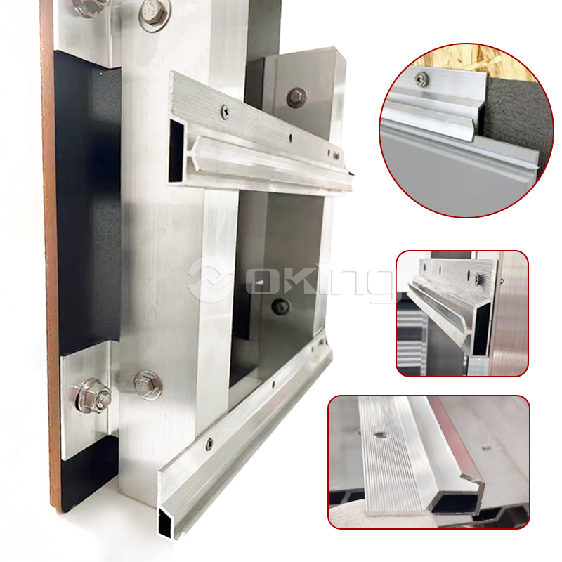
A curtain wall bracket is a short structural connector that transfers every load on a cladding panel into the primary structure through a cast-in channel or a post-fixed anchor. It carries wind suction and pressure, panel self-weight, thermal movement and seismic drift, and it has to do all of that while staying adjustable until the panel line is finally locked off.
A curtain wall bracket is a formed steel or extruded aluminium component, usually 60 to 250 mm in projection, fixed to a slab edge or into a cast-in anchor channel. It carries panel dead load in bearing or shear and resists wind and seismic actions in bending.
Reliability depends on the entire load path staying continuous and predictable, not on any single part being oversized:
A bracket rated at 3.5 kN does not deliver 3.5 kN if the anchor behind it sits 40 mm from a slab edge. The load path is only as reliable as its weakest interface, and on most projects the weakest interface is the one built on site rather than in the factory.
Reliability at the bracket-to-anchor interface comes down to three numbers: slot length, shim thickness and tightening torque. Get those right and a facade absorbs 20 mm of concrete deviation without a single panel being re-cut.
An adjustable stainless steel bracket with a 20 mm slot and a 3 mm shim stack covers roughly 10 mm laterally and 15 mm vertically. On a 3.6 m floor-to-floor grid that is the difference between a 16 mm reveal and a 4 mm reveal on the same elevation, which is why adjustable brackets have largely replaced welded fixed cleats on semi-unitised systems.
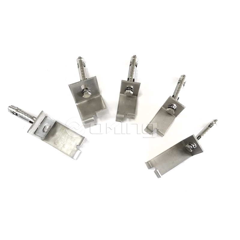
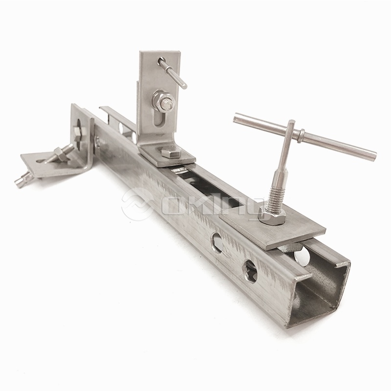
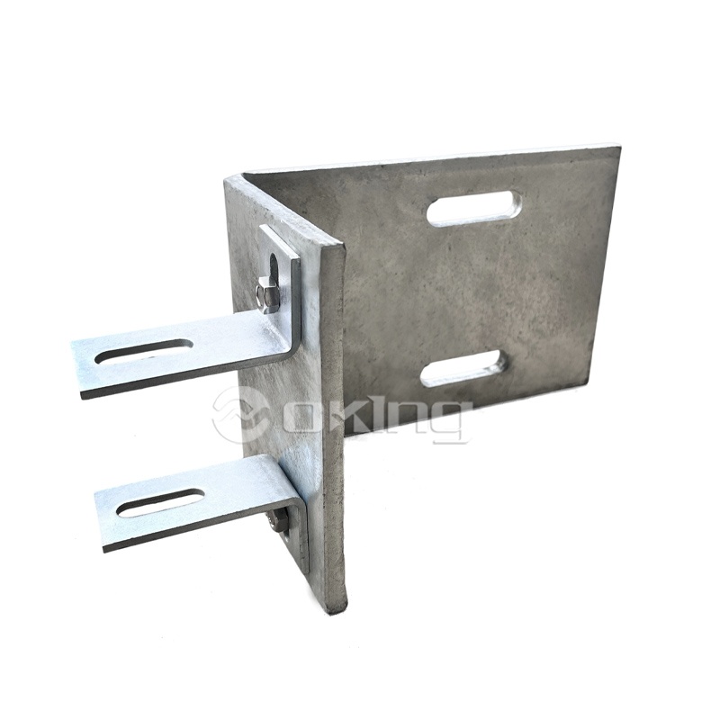
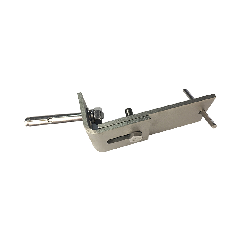 Stainless Steel Adjustable L Angle for Cladding SystemsProvides three-axis adjustment (±15/20/10 mm) for ventilated facades and curtain walls, replacing welded fixed cleats where substrate irregularities require setting-out precision.View Product →
An adjustable bracket does not repair a structure that is out of tolerance. It converts a geometric problem into a setting-out problem, and setting-out problems are solved with a laser level and a survey sheet, not with a longer slot. Once the slot is consumed, the remaining options are packers, which move load off-axis, or re-drilling, which damages the anchorage zone.
Two practical rules follow. Never design a bracket to sit at the end of its slot; keep at least 5 mm of travel in reserve in both directions. And confirm torque against the anchor manufacturer's declared value rather than against habit, because a stainless T-bolt in a channel and a through-bolt in a slotted plate need different values.
Cast-in anchor channels deliver the most reliable bracket interface on new-build concrete because the anchor position is set before the pour, which removes drilling damage, reinforcement clashes and edge-distance surprises from the critical path.
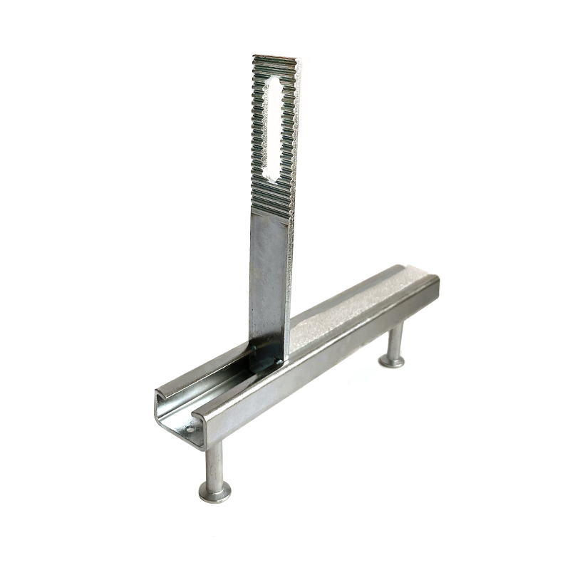
 Hot Dip Galvanized Cast-In Anchor Channel for ConcreteSet before the pour to eliminate drilling damage and edge-distance surprises, providing adjustable bracket anchoring for facades and curtain walls on new-build concrete.View Product →
The trade-off is documented in detail in this cast-in channel versus traditional anchoring comparison, which sets out the installation sequence and the checks that separate the two systems.
Bracket deflection, not bracket strength, usually governs exterior cladding support. A bracket that stays comfortably below yield but sags 6 mm at the panel fixing will still crack a stone joint and open a rainscreen lap, and no upgrade in material grade repairs that.
Most facade specifications cap bracket deflection at L/180 of the projection or 3 mm, whichever is lower, measured under the characteristic wind load defined in EN 1991-1-4. For a 200 mm projection that works out at 1.1 mm, which is why brackets that look generous on a shop drawing often fail the serviceability check even when the stress check passes.
Design the bracket for stiffness first, then check it for strength. The reverse order produces facades that pass the calculation and leak in service.
| Bracket configuration | Typical projection | Governing check | Typical section |
| Up-and-down kerf bracket | 60 to 120 mm | Bending at the kerf slot | 304 stainless, 4 to 6 mm |
| Z-type stone anchor | 80 to 150 mm | Leg bending and weld throat | 316 stainless, 5 mm |
| Adjustable L bracket | 100 to 250 mm | Deflection under wind load | 6063-T6 aluminium |
| Channel with T-bolt | 80 to 200 mm | Anchor pull-out and edge distance | HDG channel, A4 T-bolt |
Anchor design follows EN 1992-4, which for a typical mechanical anchor requires an edge distance in the region of 1.5 times the effective anchorage depth. On a 200 mm slab edge with a 60 mm cover zone that single rule eliminates more bracket positions than any wind calculation, and it is the reason the working method in this bracket load capacity calculation guide starts from geometry rather than from load.
Six steps control almost every bracket-related callback: set out from the control line, fix the base, adjust the face, shim, torque and record. Skipping the last two is what turns a 20-minute bracket into a two-week remediation.
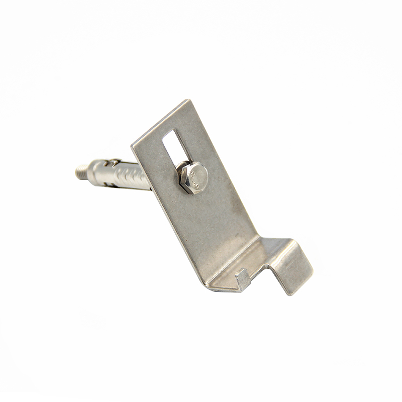 Stone Cladding Up and Down Fixing Anchor BracketConnects upper and lower stone panels with ±15/10 mm adjustment and thermal expansion compensation, ensuring seismic integrity and precision alignment for high-rise facades.View Product →
Aluminium expands about 23 microns per metre per degree Kelvin. A 3 m aluminium bracket rail therefore moves roughly 0.7 mm for every 10 degrees Celsius of surface temperature swing, which is why slotted connections and not fully welded ones carry long runs.
Finish selection follows the corrosivity category of the site under EN ISO 12944, not the architect's colour preference. The category, not the budget line, decides whether a bracket survives 25 years or shows red rust at year six.
| Exposure category | Recommended finish | Practical note |
| C2 to C3 inland urban | Electroplated zinc or 304 stainless | Acceptable where coating thickness is verified per batch |
| C4 industrial and coastal | Hot-dip galvanized per ISO 1461, 85 microns | Minimum average applies to steel 6 mm and thicker |
| C5 marine splash zone | 316 (1.4401) stainless | Molybdenum content resists chloride pitting |
| Pool and de-icing salt | 316 stainless, passivated after fabrication | Welds and cut edges need pickling and passivation |
Values are indicative envelopes drawn from finisher test data. Confirm against project-specific ISO 9227 reports for the actual coating thickness supplied.
A bracket submittal missing any of the following seven items will be returned by most facade consultants, and the delay usually runs four to six weeks on a live programme.
A bracket schedule that specifies only material and projection is not a schedule. It is a drawing note, and it will be interpreted differently by each installer on the elevation.
Provide at least 20 mm of slot travel in the direction of the concrete tolerance and keep 5 mm of reserve after setting out. That covers the 10 to 15 mm positional deviation permitted by EN 13670 on typical cast-in elements without resorting to packers.
304 (1.4301) suits C2 and C3 inland locations. Specify 316 (1.4401) for C4 and C5 exposure, coastal sites and any location within 1 km of salt water, because the molybdenum addition raises resistance to chloride pitting.
Stiffness controls. Deflection limits of L/180 or 3 mm, whichever is lower, are reached long before the 170 N/mm2 yield strength of a 6063-T6 aluminium extrusion becomes critical on a typical 200 mm projection.
By recording what was installed, not by re-calculating. Torque value, projection, anchor depth and anchor edge distance should be logged for every bracket position, and pull-out testing to the project sampling rate confirms the anchorage rather than the bracket.
A reliable exterior wall cladding system is not defined by the strongest bracket on the schedule. It is defined by the interface that was measured, adjusted and recorded on the day it was fixed.

We will wholeheartedly provide you with high quality products, reasonable price, on-time delivery and attentive service.
Maoshan Taiwan Business Industrial Park, Dinan Town, Xinghua City, Jiangsu Province, China

+86-523-82799922

+86-15996094444

+86-523-82799933


Copyright © Jiangsu Aozheng Metal Products Co., Ltd. All Rights Reserved.
 English
 русский
 Español
 عربى


Contact Us